Factory Automotive Wiring Diagrams
Contents
Factory Automotive wiring diagrams or electrical schematics are a fantastic way to help one navigate through a wiring job or any type of wiring diagnosis on a vehicle. Sometimes an automotive wiring diagram is needed for something as simple as wiring in a car stereo or something as complicated as installing an engine wiring harness. Whatever the case may be, factory automotive wiring diagrams are an essential tool for getting the job done. Have you ever tried to do a wiring repair with more than a few wires without a wiring diagram? It can be very difficult. Using a wiring diagram saves you time and money.
Where to get Automotive Wiring Diagrams and Schematics
While there are many sources on the internet that you can get your hands on factory automotive wiring diagrams and schematics, there are two places that I have found reliable without a doubt. They are Alldata and Mitchell on Demand. Both are a small one-time fee but both have very good customer support that will help you locate the correct wiring diagram and repair information you’re looking for within their system. Sometimes you can Google certain wiring diagrams but I have found they never come back accurate. There are so many variables that can affect the wiring diagram you don’t know if it is reliable or not. It just pays to know you are using the right wiring diagram.
If you’re having electrical issues with your vehicle and would like to speak with a specialist, click here and enter all the details.
How to read Automotive Wiring Diagrams and Schematics
There are a lot of things to consider when looking at automotive wiring diagrams or electrical schematics. I will start with the absolute basics. The top of the wiring diagram usually indicates where the “power” is coming from for the specific component. For example, if you are looking at a wiring diagram for a fuel pump, the power source is going to be at the top of the page. Either a relay, fuse or the power distribution center where the electrical component gets its power. Most of the time, if you are looking at a power distribution wiring diagram, the power source will be located at the top of the page. Main fuses or even battery supply. The bottom of the page is the Ground for the specific component. Sometimes components will share a common ground and sometimes they will not. Assuming all of the grounds are good, they will all eventually lead back to the same place.. the battery.
In some cases, the diagrams are laid out so it goes from the left to the right. (Some Toyota wiring diagrams are laid out this way). This is usually not the case but it does happen and it is very easy to read. (I think I even prefer it this way)
Here is a good beginner guide to reading schematics. They also have an E download for your Kindle as well. If you want to become a pro at reading Automotive wiring diagrams, I recommend reading “Automotive Wiring and Electrical Systems” by Tony Candela.
Factory Wiring Schematic Symbols
Here is a picture of some symbols you will see when looking at an automotive wiring diagram. Some are very common and some are not so common. If you look at the top row of the picture, you will see a symbol of a battery, fuse, circuit breaker, and fusible links. These are all very common and it is important to know what these symbols are. You will also see two arrows (one on top of another) which indicate a connector. Then it is followed up by a number assigned to it by the manufacturer. For example, C123 is connector 123. This makes it easy to locate the connector, find a pinout chart for the connector if needed, and even order a new connector from the dealership if by chance it needs to be replaced. Also, in this picture, you will see a symbol of a ground, clockspring, open and closed switch, oxygen sensor, resistor, one-speed electric motor, two-speed electric motor, reversible electric motor, and more.

Automotive wiring diagram Acronyms
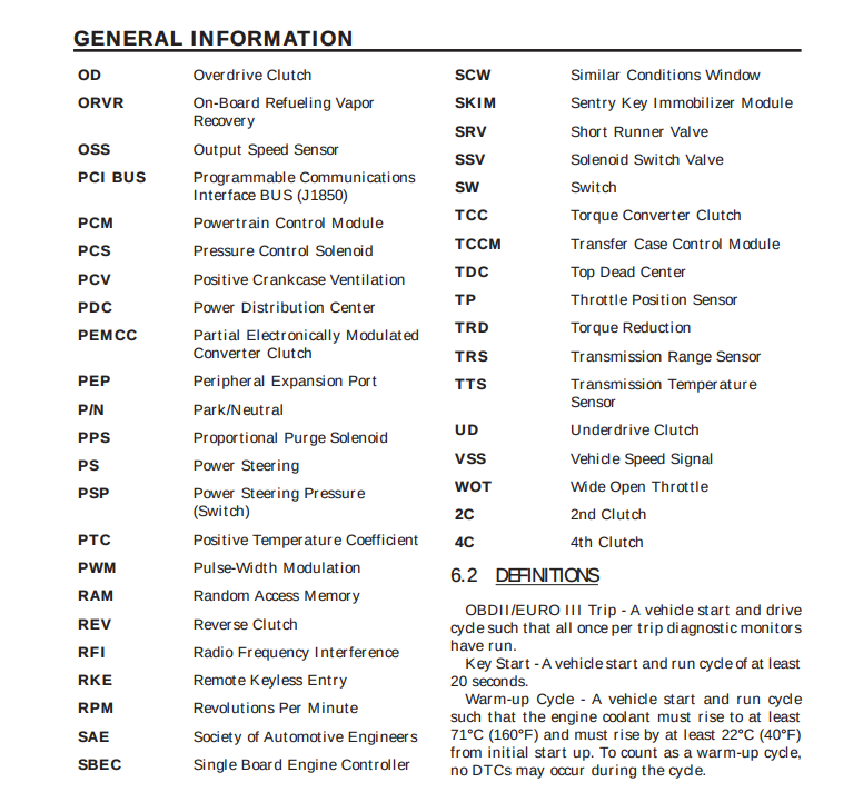
Here are some common Acronyms you might see when looking at an automotive wiring diagram. The picture is specific to Dodge, Jeep, and Chrysler vehicles. Some common ones I see every day when looking over wiring diagrams or electrical schematics are PCM, SKIM, PCI BUS (which is the communication networking between all modules on board the vehicle), PS, PSP, VSS, OSS, TRS, PDC and more.

Voltage check
Connect the black lead of a voltmeter to a known good ground and then connect the red lead of the voltmeter to the selected test point and take a reading. It is as simple as that. I recommend an Auto-Ranging Fluke Digital Multimeter. If you have a manual setting meter, it needs to be set to the 20-volt DC scale. Depending on the circuit you are testing, the ignition switch may need to be turned “ON” to get a voltage reading. The voltmeter will display the difference between the two leads. For example, taking a voltage reading at the battery with it fully charged at 12.6 volts, the voltmeter will display the difference between the positive and negative post or terminal and will display the 12.6-volt reading.
Continuity Test
Checking for continuity should always be done when there is no voltage within the circuit. For example, the circuit is not in use, or even the battery is disconnected. Remove the fuse for the circuit being checked or disconnect the battery. Connect one lead of the ohmmeter to one side of the circuit being tested. Connect the other lead to the other end of the circuit being tested. Low or no resistance means good continuity.
Checking for A Short To Ground
Remove the fuse and disconnect all items involved with the fuse. Connect a test light or a voltmeter across the terminals of the fuse. Starting at the fuse block, wiggle the wiring harness every 6 to 8 Inches and watch the voltmeter/test light. If the voltmeter registers voltage or the test light glows, there is a short-to-ground in that general area of the wiring harness.
Voltage Drop testing
Connect the positive lead of the voltmeter to the side of the circuit closest to the battery. Connect the other lead of the voltmeter to the other side of the switch or component. Operate or turn “on” the electrical circuit. This will “load” the circuit. Remember, the voltmeter will show or display the “difference” in voltage between the two points. So if the circuit is good and there is no loss of voltage when the circuit operates and the voltmeter will display a reading of 0 volts. However, if there is a bad connection preventing the circuit from working, the voltmeter may display a reading of 12 volts or battery voltage. Any reading above 1 or 2 volts is considered “bad” or “too high” when doing a voltage drop.
Chrysler wire Colors Codes
BL = Blue
BK = Black
BR = Brown
DB = Dark Blue
DG = Dark Green
GY = Gray
LB = Light Blue
LG = Light Green
Or = Orange
PK = Pink
RD = Red
TN = TAN
VT = Violet
WT = White
YL = Yellow
Ford wire Color Codes
BU Blue
BK Black
BN Brown
DB Dark Blue
DG Dark Green
GN Green
GY Gray
LB Light Blue
LG Light
YE Yellow
NA Natural
WH White
TN Tan
SR Silver
RD Red
VT Purple
PK Pink
OG Orange
Nissan wire Color Codes
B = Black
W = White
R = Red
G = Green
L = Blue
Y = Yellow
LG = Light Green
BR = Brown
OR or O = Orange
P = Pink
PU or V (violet) = Purple
GY or GR = Grey
SB = Sky Blue
CH = Dark Brown
DG = Dark Green
Toyota wire Color Codes
B = Black
W = White
BR = Brown
L = Blue
V = Violet
SB = Sky Blue
R = Red
G = Green
LG = Light Green
P = Pink
Y = Yellow
GR = Gray
O = Orange
Honda Wire Color Codes
BLK = Black
BLU = Blue
BRN = Brown
GRN = Green
GRY = Gray
LT BLU = Light Blue
LT GRN = Light Green
ORN = Orange
PNK = Pink
PUR = Purple
RED = Red
WHT = White
YEL = Yellow
NAT = Natural
Wiring diagrams for the following systems…
Antilock Brakes / Traction Control Systems, Brake Warning Indicator, Cruise Control, Heated Glass Element, Heating and Air Conditioning, Instrument Panel, Gauges and Warning Indicators, Lighting and Horns, Mirrors
Power Locks, Powertrain Management, Radiator Cooling Fan Motor, Radio, Stereo, and Compact Disc, Seats, Starting and Charging, Trailer Adapter Kit, Transmission, and Drivetrain, Windows, Wiper and Washer Systems
- Ford factory wiring diagrams and electrical schematics
- GM/Chevy factory wiring diagrams and electrical schematics
- Chrysler factory wiring diagrams and electrical schematics
- Toyota factory wiring diagrams and electrical schematics
- Honda factory Wiring diagrams and electrical schematics

